Building an 8-Bit CPU on a Game Boy
I recently finished building Ben Eater’s 8-bit Breadboard Computer but near the end of it I realized that much of the fun was in the design and the learning, but the act of actually cutting wire was an exercise in tedium.
I wasn’t quite ready to put the 8-bit computer behind me, but I didn’t want to cut or bend wire anymore.
Another thing that’s been on my to-do list is programming for the original Game Boy (GB). The GB comes from a time when game development was a lot closer to the hardware: developers had to be intimately familiar with the hardware, not only because they were writing in assembly and needed to understand the quirks, but because it was necessary to squeeze every last bit of performance out of relatively weak machines.
The entire system is simple enough that you can understand how it all works from top to bottom, but powerful enough to actually do cool stuff. If you doubt its power, look at a game like The Legend of Zelda: Link’s Awakening.
Modern game development involves writing C++ for huge game engines like Unreal Engine where you can’t possibly understand how everything works. Instead there are layers above and below your code, and you’re mostly just inserting little glue layers in-between.
The Game Boy is an intersection of two of my interests: game development and low-level hardware stuff. It’s essentially a self-contained embedded system (8-bit CPU, buttons, speakers, RAM, timers, interrupts, memory-mapped IO, LCD) with the capability of game development (sound effects, sprites, tilemaps).
There is also a large amount of documentation around the GB on the net which makes it relatively easy to get started (but hard to master). The primary resource is gbdev which contains Pan Docs (the technical reference), RGBDS (tools for assembling), and links to tutorials.
Game Boy SAP-1
While staring at my (mostly) complete build of the 8-bit breadboard computer and pondering what to do next (besides fixing the final bug that haunts me), I had the idea of recreating it on a Game Boy as a fun and relatively simple way to ease myself into GB development.
The 160x144 display could display the LEDs as tiles. The buttons could act as pushbuttons and potentiometers and switches. The DIP switches could exist virtually and be set with the d-pad. The internal timer could work as the auto clock step.
Essentially I could emulate the computer on the GB, but with the added flair of visualizing the LEDs (that’s the coolest part of the breadboard computer).
Process
I first laid out the display in a spreadsheet to make sure that everything I wanted would fit onto the screen which could display 20x18 tiles of size 8x8.
I went through a few iterations until I was able to fit everything on the screen in a way that was still clean and legible. It would have been nice to put everything in the same location as they exist on the breadboards but there simply wasn’t enough horizontal space.
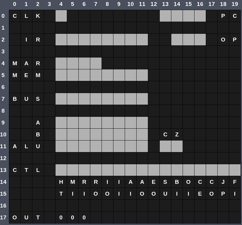
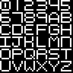
I designed a font where each glyph is one tile. I don’t claim to be the world’s greatest type designer, but it gets the job done.
And of course I needed an LED. I went for a square with rounded corners which reads nicely on the small display.

With the layout and tiles designed, it was time to get it all displayed on screen. But you can’t just put a PNG on the Game Boy and expect it to display it. Each tile is eight rows of 8 pixels, and each row is two bytes, for a total of 16 bytes per tile.
The original Game Boy had 2bpp color, meaning it could display four colors: white, light gray, dark gray, and black; although these shades of gray displayed on the original as shades of green.
Pixel N in the tile has its color determined by combining bit N of Byte 1 with bit N of Byte 0, and the resultant value is an index into the palette. For example, the digit 0 of the font:
83 83 7D 7D 6D 6D 6D 6D 6D 6D 7D 7D 83 83 FF FF
Each pixel is either fully black (0x3) or fully white (0x0).
The first line is defined by the bytes 83 83:
    1000 0011

    1000 0011
-------------
    3000 0033
Reading left to right, that means the order of pixels goes black, white, white, white, white, white, black, black, which is exactly what the image shows. You can read more about it here.
Needless to say, that would all be tedious to calculate by hand so I used the wonderful tool called Gameboy Tile Data Generator (gbtdg). You give it an 8x8 PNG and it generates the 16 bytes that the GB expects.
The LED and font tiles can then be put into the ROM.
| |
And the map can be defined as indices into the list of tiles, where tile $00 is the blank (black) tile.
| |
I’ve truncated some empty offscreen tiles here to help everything fit better on screen but the code has the full version.
I fill the entire tile map rather than just the 20x18 tiles that are on screen. The actual full Game Boy tile map is 32x32 which allows for rendering things off screen before displaying them (by modifying the viewport). Storing all 32x32, with unused tiles as blank, allowed me to just write from Start Address to End Address easily without doing any offsets (see below).
The use of TileMap_Begin and TileMap_End is a convenient method of assigning names to addresses which can be used to do things like count the number of bytes in a section (TileMap_End-TileMap_Begin).
Displaying the tiles on screen involves first loading the tile descriptions (the sixteen bytes per tile) into VRAM (given the mnemonic _VRAM). Tile 0 is stored at address _VRAM, Tile 1 at _VRAM+16, Tile 2 at _VRAM+32, etc. Here that means blank is $0, digit 0 is $1, digit 1 is $2, and so on up until the enabled LED tile is $26.
| |
With the tiles in VRAM, we can fill the tile map (given the mnemonic _SCRN0) by copying the full 32x32 tile map shown above. That’s why I wasted the space filling out the offscreen regions; it allows for code that starts at TileMap_Begin and ends at TileMap_End, without needing to skip the offscreen bytes. We aren’t starved for bytes with this project anyway.
| |
The code uses a subroutine called CopyBytes which takes a source address, destination address, and a byte count, and then copies byte by byte from source to destination.
| |
There’s some other code required also to actually get everything on the screen, mainly turning off the LCD before accessing VRAM (don’t do that; either turn off the LCD or wait for VBLANK);
| |
That’s essentially all that’s required to get the initial state of everything onto the screen.
Emulation
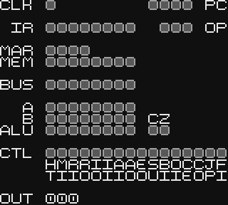
The majority of the work was actually emulating the CPU operations which meant breaking down the instructions into their two parts (4 bits of opcode and 4 bits of optional data), tracking the current op stage, and then asserting different signals depending on the stage.
Let’s step through the instruction LDA 14, where the opcode is $1 and the data is $E, which is 0b00011110. This instruction loads whatever is in memory at address 14 ($E) into the A Register.
| |
Every instruction has the first two stages:
Stage 0
- CO: Put the value in the Program Counter onto the bus
- MI: Load the value on the bus into the Memory Address Register
Stage 1
- RO: Put the value that’s in RAM at the address in the MAR onto the bus
- II: Put the value in the bus into the Instruction Register
- CE: Increase the value in the Program Counter
These two steps are the Fetch. They fetch the next instruction from memory and put it into the Instruction Register.
In code, that means looking at the current op stage opc (which is initialized to 0), executing stages 0 and 1, and then branching elsewhere at stage 2 and beyond.
The control signals take up two bytes (16 bits), where each bit represents the state of one signal, so asserting one is as simple as using the set instruction to enable the bit that corresponds to that signal. ctrl is the address of the first byte and ctrl+1 is the address of the second.
To determine the instruction and thus the next stage is done by masking the upper four bits (and $f0) and jumping to the appropriate instruction based on the value.
| |
Once the opcode is determined we call the corresponding function. In this case LDA.
When it comes time to evaluate the actual instruction, all it needs to do is set the appropriate signals based on what stage of the instruction it’s in. For LDA, that’s different for Stage 2 and Stage 3. There is no Stage 4.
Stage 2
- IO: Put the lower four bits of the Instruction Register onto the bus
- MI: Load the value on the bus into the Memory Address Register
Stage 3
- RO: Put the value that’s in RAM at the address in the MAR onto the bus
- AI: Put the value on the bus into the A Register
| |
All of the actual work is done at the end of the tick depending on whichever signals have been asserted by the current stage of the current instruction. The order of execution matters because any signal that puts data somewhere must be evaluated before any signals that need to read that data.
| |
Each signal subroutine checks if its respective bit is set in ctrl or ctrl+1 and, if it is, does its thing. Stage 2 of LDA 14, for instance, will have IO and MI set so ctrl_io will put the value in RAM onto the bus first, and then ctrl_mi will load that into the Memory Address Register.
| |
Finally all of the LEDs are updated to display the current values, as well as the digits of the output register.
The subroutine UpdateLeds toggles LED tiles based on a binary value so that a high bit displays as an enabled LED and a low bit displays as a disabled LED. It works for an arbitrary number of LEDs by shifting the value left and seeing if a 1 or a 0 shifted out (which sets the carry flag).
| |
Displaying the output as three digits meant converting a binary value to Binary-Coded Decimal (BCD) so that each digit could be represented as a single tile.
CalculateBCD does so by dividing by 100 until overflow and saves the number of divisions (the 100s place), then divides by 10 until overflow and saves the number of divisions (the 10s place), and then subtracts the remaining value to get the 1s place.
| |
Limitations
There are two parts to the program: the emulation, which just interprets the opcodes and performs the required action (e.g., LDI N will load the value N into the A register); and the LED simulation which ensures that the correct LEDs light up on screen at the same time as they would on the actual breadboard version.
The circuit that exists on the breadboard involves a lot of signals that operate simultaneously, but the GB’s CPU can only execute one instruction at a time. Achieving correct behavior as well as correct LED display required checking/executing signals in a specific order (which isn’t an issue on the breadboard because multiple signals can fire simultaneously).
On the breadboard the output signals put a value on the bus lines as soon as that signal is asserted and the input signals latch that value on the rising edge of the clock. So if AO is asserted, then the value in the A register is on the bus lines. And if OI is also asserted, then the value on the bus lines will go into the output register once the clock pulses.
The solution is simply to evaluate the output signals (RO, IO, AO, etc) before evaluating the input signals (MI, RI, AI, etc), so that the variable holding the bus value has been loaded before being read.
Making sure the state of the LEDs was correct during development mostly involved loading the GB version with the same program as Ben, watching him step through in his videos, and making sure the LEDs matched.
The Zen of Assembly
Even experienced programmers often fear assembly. I was surprised to discover that I found it mostly enjoyable.
It’s Fun
Programming in assembly turned out to be very therapeutic. Being able to understand the GB’s architecture and create behavior one instruction at a time was a welcome change from wrangling C++ and OOP.
There are no libraries, no compiler black magic, no hidden behavior, no fighting the language. It’s just you, the assembler, some registers, and a bunch of data.
Programming is, after all, just data manipulation which is often obscured by modern languages.
Stack and Registers
The usual stack-based approach to a function would be to push any registers you’re going to use onto the stack, use them however you want, and then pop the old values off the stack before returning. Or allocate space on the stack for local variables and function parameters.
But, while the Game Boy has a stack, using it is discouraged because pushing and popping takes a lot of machine cycles. I avoided pushing and popping whenever possible and instead tried to write all functions using nothing more than the given registers. If I needed to use a register in the function but its old value was important (common with A), I would try to save it to a separate register that wasn’t needed and then restore it at the end. This allowed me to avoid using the stack for all functions except interrupt handlers.
Interrupt handlers require use of the stack because you don’t know when they’re going to be called so you don’t know which registers are safe to use. In that case you must push any registers you’re going to overwrite onto the stack and pop them at the end.
You can see such a situation in the UpdateTiles function which is called when a VBLANK interrupt occurs. I use the A register extensively and so I push it (as well as the flags register because you can only push/pop 16-bit register pairs but also because flags are often important to preserve) before doing anything with A.
| |
Prefer Relative Jumps
The Game Boy has two types of jumps: jump absolute (jp) and jump relative (jr). The absolute jump will jump to a 16-bit address while the relative jump can jump -128 locations backward or +127 locations forward. In other words, if you’re at PC $205 and do a jr 5, it’ll go to $20A, and if you do jr -5 it’ll go to $200. (The assembler handles the offsets for you; you can just use a label as a destination.)
Relative jumps should be the first choice at all times because they take fewer cycles to execute and they use fewer bytes (8 bit offset instead of a 16 bit address). I used jr by default at all times and then would only change to jp once the assembler told me I had an error (due to the label I was trying to jump to being too far away).
Loops and Falling Through
When doing conditional logic it was often useful to think in terms of falling through conditions as a way of simplifying the logic.
As an example, here’s code for checking if the A button is pressed. It calls ReadKeys which loads A with four bits indicating Start, Select, B, and A; then it checks for bit 0 (A). If it’s set, the nz flag is set, so it jumps to key_pressed. Otherwise it jumps to key_released.
| |
But we can simplify it by shuffling things around:
| |
Or by changing the logic:
| |
In both cases the flow of execution falls through to the “else” case, which removes the need for two jr instructions for each case.
Setting to 0
It’s common to want to set some value to 0. The obvious way is with ld:
| |
But there’s another way:
| |
1 XOR 1 is 0 and so XORing two values that are the same will be all zeros because all of the same bits are set.
    01010111
XOR
    01010111
------------
00000000- ld r,n takes 8 clock cycles and uses 2 bytes.
- xor a takes 4 clock cycles and uses 1 byte.
It’s simple tricks like this that can save a lot of space and cycles when you use them a lot in a large program/game.
Result
The following is the program that runs in the video titled “Conditional jump instructions” which counts from 0 to 255 and back to 0 again repeatedly. I made a slight modification and changed it to count in increments of 15 to make it go faster.
| |
The computer only has 16 bytes of RAM. The program itself takes up the first 8 bytes, and one more byte is used as for actual variable data (address 15 which contains the value 15).
Here it is running at a slow speed in the bgb emulator so that you can see the LEDs clearly.
We can also crank it up a bit.
But the true test is running it on real hardware. I have a Game Boy Color that has been fitted with a backlit IPS LCD (because I can) and an Everdrive GB X7 for running ROMs.
In all of the videos you can see that the clock LED doesn’t work quite right. It simply cycles too fast to be accurately represented on screen.
The Future
There are some features I’d still like to add:
Game Boy Color support
Monochromatic LEDs are a bit boring. I’d like to add color so that the LEDs match those of the breadboard version (blue for bus, red for ALU, yellow for control, etc).
Programmable at Runtime
The program is embedded directly inside the ROM, so if you want to change it you have to edit the source and rebuild. The breadboard is programmed with DIP switches and the same could be done on the Game Boy: boot into a programming menu with an address DIP switch and a data DIP switch, set them both, then press a button to program it. When finished, press another button to go into Run Mode.
Dynamic Clock Speed
The clock speed is set in the source and changing it again means rebuilding. It would be nice to be able to increase and decrease the clock as the program runs, as well as being able to select Auto or Manual modes.
Source Code
The source code is here.
Last Edited: Dec 20, 2022