Building an FPGA Computer: VGA
When I set out to build a simple computer with an FPGA ( here, here, and here), my end goal was always to display something on a computer monitor.
VGA was a natural choice because it’s simple and analog, rather than the complex digital nature of something like HDMI. All you have to do is place voltages on some pins at a specific frequency and the monitor is able to interpret it as colors displayed at a certain resolution.
Pins
There are three VGA pins to represent color: one for red, one for green, and one for blue. The minimum voltage on each can be 0V and the maximum voltage can be 0.7V, meaning that we’re dealing with analog values here, not digital.
The TinyFPGA-BX only has a limited number of exposed pins so we’ll go with 8-bit color encoded as RGB332: 3 bits of red, 3 bits of green, and 2 bits of blue. Blue has the fewest number of bits because the human eye is least sensitive to it so it’s better to use the bits elsewhere. That allows for 256 colors, with more in the red and green part of the spectrum.
Three pins from the FPGA represent red, another three for green, and then two for blue. The three pins of red need to be mixed together to go from 000 (0.0V) to 111 (0.7V). The same is true for green. But for blue the two pins need to be mixed together to go from 00 (0.0V) to 11 (0.7V).
However, an FPGA exists solely in the digital domain: we can either put a one (maximum voltage) or a zero (minimum voltage) on a pin, but not something in the middle. But there is a way to convert digital values into analog ones using resistors called a resistor ladder.
For red there are eight possible combinations of the three digital pins to represent the range from 0.0V to 0.7V, which makes for easy math to determine what voltage we want for each of the eight combinations.
| R2 | R1 | R0 | Voltage |
|---|---|---|---|
| 0 | 0 | 0 | 0.0 |
| 0 | 0 | 1 | 0.1 |
| 0 | 1 | 0 | 0.2 |
| 0 | 1 | 1 | 0.3 |
| 1 | 0 | 0 | 0.4 |
| 1 | 0 | 1 | 0.5 |
| 1 | 1 | 0 | 0.6 |
| 1 | 1 | 1 | 0.7 |
The same is true of green.
| G2 | G1 | G0 | Voltage |
|---|---|---|---|
| 0 | 0 | 0 | 0.0 |
| 0 | 0 | 1 | 0.1 |
| 0 | 1 | 0 | 0.2 |
| 0 | 1 | 1 | 0.3 |
| 1 | 0 | 0 | 0.4 |
| 1 | 0 | 1 | 0.5 |
| 1 | 1 | 0 | 0.6 |
| 1 | 1 | 1 | 0.7 |
Blue is similar but there are only four combinations of the two pins.
| B1 | B0 | Voltage |
|---|---|---|
| 0 | 0 | 0.00 |
| 0 | 1 | 0.23 |
| 1 | 0 | 0.47 |
| 1 | 1 | 0.70 |
The output pins of the FPGA are 0V when logic low and 3.3V when logic high. By using the principles of adding resistors in series and parallel, and rounding values to the nearest physical resistor values, we get this combination of resistors which will translate from 0.0V and 3.3V to some value in between 0.0V and 0.7V, for each of the R/G/B channels:
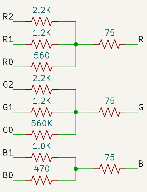
Besides the values of the eight resistors on each of the color channels, there is also 75Ω of impedance on each of the color pins outside of our circuit, which has been factored into the calculations when determining the eight resistor values.
There are two more pins which are necessary: H-Sync and V-Sync, which will be discussed in the next section. They don’t need any resistors and can be hooked up directly from the FPGA to the VGA connector.
Timing
As mentioned earlier, VGA is an analog standard, which makes it easy to get up and running. But VGA supports many different resolutions and refresh rates, so how do the computer and the display agree on which resolution/rate combo is being used?
It all comes down to signal timing. The computer sends H-Sync and V-Sync pulses at a specific frequency and the display understands that frequency as a way of representing a specific combination of resolution and refresh rate.
For example, the “industry standard” is 640x480 @ 60Hz which expects pixels to tick at a rate of 25.175MHz. There is a visible area of 640x480 but there are “hidden” pixels outside of that region which are not shown on the display but are instead used for timing. As shown on the page, there are 96 pixels of horizontal sync where the h-sync line should be low, and 2 pixels of vertical sync where the v-sync line should be low. It’s the timing of those two signals (3.81us for h-sync and 0.06us for v-sync) which inform the monitor of the proper resolution and refresh rate to use.
Luckily all of that is very easy to translate into an FPGA.
| |
hsync is low when the x-coordinate of the current pixel is within the 96 pixel interval for H-Sync and vsync is low when the y-coordinate of the current pixel is within the 2 pixel interval for V-Sync. Other than that it does nothing more than increment the current x- and y-coordinate to track which pixel is currently being displayed. When it hits the end of a line (the full line, not just the visible line) it increments Y and sets X back to 0. When it hits the very last line it sets Y back to 0.
There’s nothing more to keeping the computer and the display in sync; it’s entirely done by the timing of the hsync and vsync signals.
But what about the clock? The TinyFPGA board has a 16MHz clock but 640x480@60Hz requires a pixel clock of 25.125MHz, so we wouldn’t be able to toggle the sync pins fast enough to get the display into our desired mode.
The FPGA has something called a Phase-locked Loop (PLL) which allows for turning a slow clock into a faster one. Using the icepll tool, we can generate a PLL module automatically, telling it that we have a 16MHz clock and want to get a 25.125MHz clock out of it.
| |
That generates the following Verilog module:
| |
It wasn’t able to give us exactly 25.125MHz, only 25.000MHz, but that’s close enough to work. Some monitors may be more picky than others, but the Dell that I’m using is okay with that frequency.
| |
We connect the physical FPGA pins that connect to the VGA connector (8 pins for color, 1 hsync pin, 1 vsync pin) and give vga_hsync and vga_vsync to the VGA module so that it can toggle them as necessary. vga_x and vga_y aren’t necessary to talking to a display, they’re just there so that when we want to draw we know which pixel is currently being drawn.
Drawing Something
That’s everything that’s needed to talk to a VGA display, so all that’s left is setting the color and seeing it on screen. For simplicity, we’ll just write a specific color when the X- and Y-coordinates are within a certain range, drawing a square. In this case, it will draw a red square in the middle and black everywhere else.
| |
Last Edited: Aug 17, 2023