An Overview of NES Rendering
I’m in the midst of creating an NES emulator and struggled at first to understand how the rendering worked at a high level. Nametable, attribute table, pattern table, background, sprites, palettes. The Nesdev Wiki has all of the info necessary but it isn’t presented in a way that clicked with me. The details were abundant but the big picture view was missing.
Cross-referencing the wiki and Nintendulator’s debug views, I put together a mental model of what’s going on. I’ll present that here.
It’s going to be high-level though, so I won’t be talking about addresses or cycle-by-cycle rendering. That’ll come later.
Overview
A frame is composed of a background and sprites. The background is fixed in place (ignoring scrolling) while sprites can be in arbitrary positions around the screen and move independently of the background.
For the following explanation we’ll be using the original Donkey Kong, an arcade game ported to the NES.
Nametable
The background is made up of a grid of tiles, each tile being 8x8 pixels. A frame is 256x240 pixels or 32x30 tiles.
The nametable describes the layout of the frame’s background. The tiles start at (00,00) in the upper left and increase downward to the right until the final tile in the bottom right at (1F,1D).
The nametable is dynamic, meaning that it can (and often does) change frame-by-frame as the CPU sends data to the PPU to fill the nametable. Each tile in the nametable contains a single byte in PPU memory.
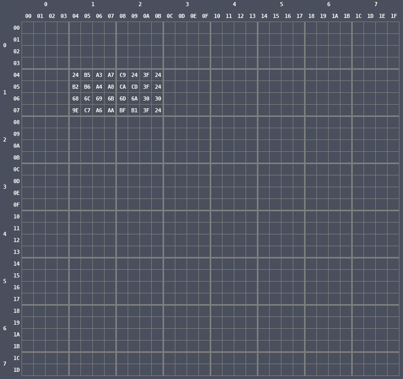
Let’s take a look at the nametable in memory when the title screen for Donkey Kong is being displayed.
The numbers across the top are the tile’s X-index and the numbers down the left are the tile’s Y-index.
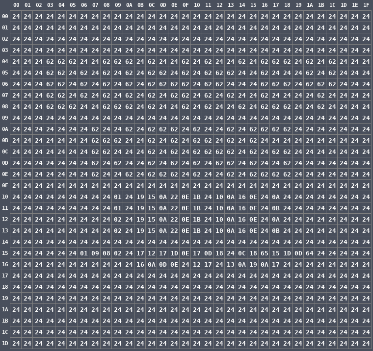
It may just look like a bunch of numbers, but there are a lot of tiles with the value 24 so let’s highlight all of the tiles that hold other values.
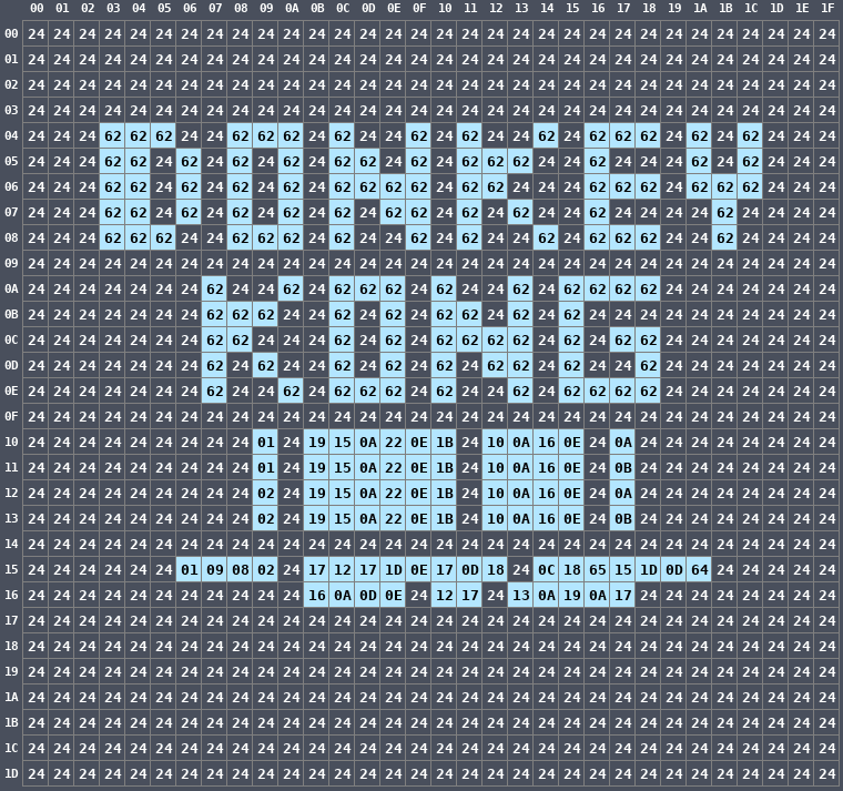
There is an obvious pattern here: the words DONKEY KONG spelled out. Each of the tiles making up the words contain the byte 62 which means nothing to us just yet.
Below are more numbers but their meaning isn’t immediately obvious.
What are those bytes? What are 62, 24, and all the rest? They’re indexes into the Pattern Table.
Pattern Table
The pattern table contains the shape of each background tile and sprite. It’s static data residing in the ROM (or cartridge on the actual NES) that the PPU can read from (but not write to). The byte in the nametable tile above is an index into the pattern table. The contents in the pattern table describe what will be displayed.
Let’s use the tile at (09,10) as an example. It contains the value 01. At index 01 in the pattern table, there are sixteen bytes. Let’s separate them into the low bytes (the first eight) and the high bytes (the second eight).
- 0-7: 18 38 18 18 18 18 7E 00
- 8-F: 00 00 00 00 00 00 00 00
That doesn’t mean anything in that form, so let’s lay them out on top of each other and display them in binary form.
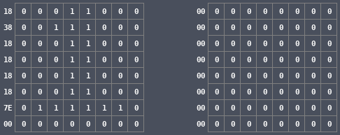
Now we combine the first eight and the second eight together to get the final pattern. I’ll highlight every 1 to better see them.

There it is: the digit 1 drawn with binary.
Let’s do the six tiles to the right of that one, from (0B,10) to (10,10), again laying out their contents on top of each other in binary form. The second eight bytes are all zeros for the entire title screen, so we’ll omit them. We’ll see later what happens when they aren’t zeros.

Next we’ll do the next four tiles from (12,10) to (15,10).

Finally the final tile in that row at (17,10).
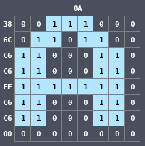
So all together that row of tiles spells out 1 PLAYER GAME A.
Let’s look at the entire frame rendered in this way.
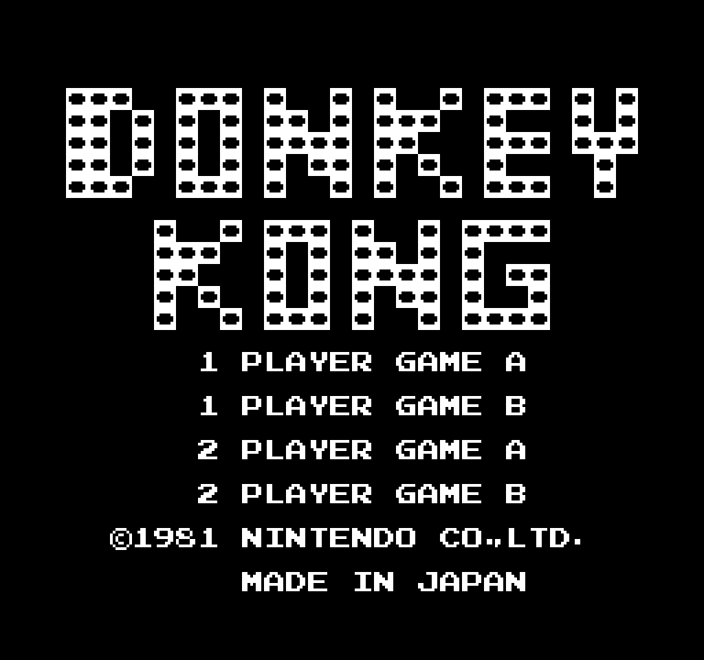
The shapes are there but we’re missing color. Drawing in binary like this results in monochrome because a pixel is either white or black.
You may think that it doesn’t look that bad monochrome. After all, the shapes are still there. But that’s only true on this title screen. Let’s see what the actual game looks like this way.
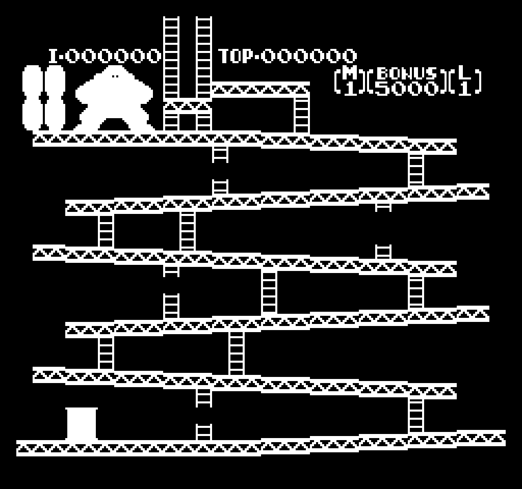
Yuck. That big blob at the top is supposed to be Donkey Kong but without colors he’s just a silhouette. The same is true of the wooden barrels next to him and the oil drum at the bottom. We need color.
System Palette
The NES has a finite set of colors that a game can use to draw pixels. Let’s call that set of colors the system palette.
The palette of the actual NES is rather complicated so many people have generated their own palettes to attempt to reproduce the true colors. We’ll use this one from the wiki.

Each color is given an index (00 to 3F) so that the game can refer to specific colors in the palette.
Frame Palette
While the system palette contains a total of 64 colors, a single frame has its own palette that is a subset of the system palette. Let’s call that set of colors the frame palette
The system palette is static but the frame palette is dynamic: the CPU sends palette entries to the PPU so different frames can use different sets of colors. But for a single frame only the colors in the frame palette can be displayed.
The frame palette is eight groups of colors of four colors each. Each group in the frame palette has an index (0 to 7), and individual colors in that group also have indexes (0 to 3). Palette 0 to Palette 3 are for the background and Palette 4 to Palette 7 are for the sprites.
For this particular frame of Donkey Kong, the frame palette looks like this:

Background Colors
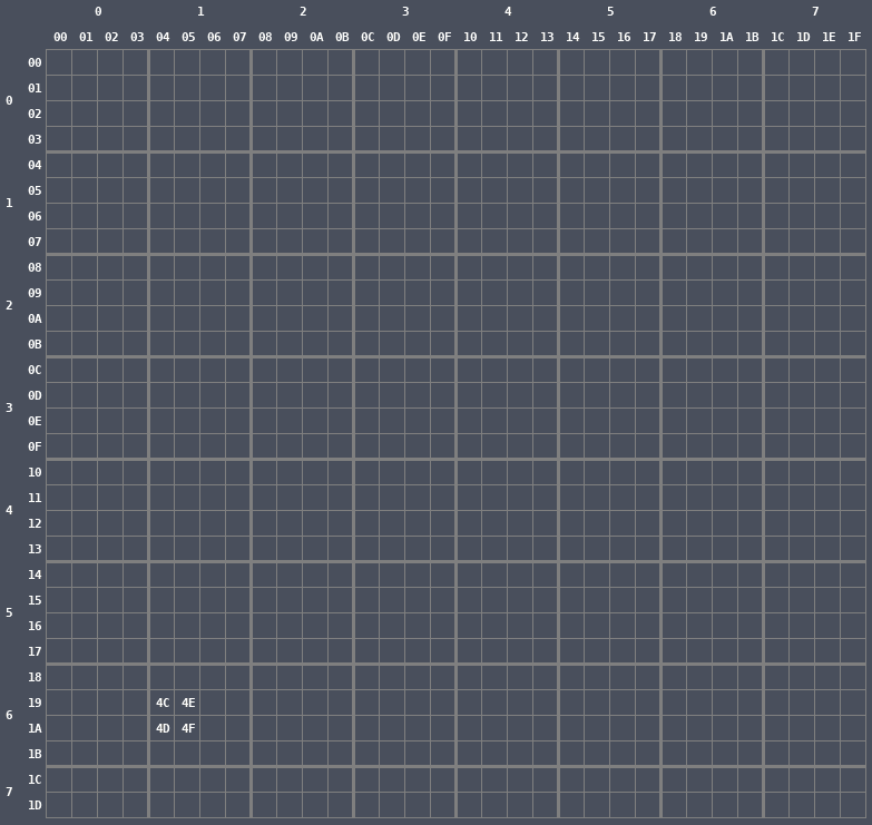
If you recall, all of the tiles on the title screen had all zeros in the second group of eight bytes in the pattern table, so the result of the combining operation with the first eight and the second eight was always either a 1 or a 0. For an example of a background object where the second set of bytes are not zero, let’s look at the oil drum at the bottom of the screen at (04,19), (05,19), (04,1A), and (05,1A). It’s composed of four tiles.
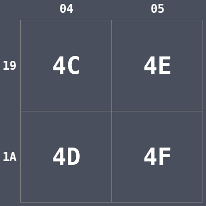
Again, we’ll take the first eight bytes in the pattern table of each of the four tiles and lay them out in their proper tile locations in binary form.
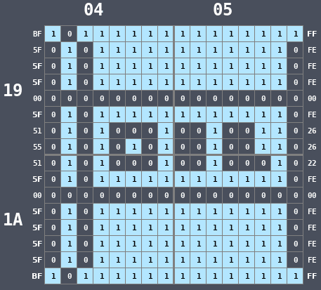
There we go, an oil drum. But this is still the monochrome version. Let’s look at the second set of eight bytes laid out in the same manner.
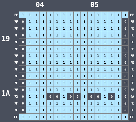
Now we combine both sets together to get a value for each pixel that is between 00 (0) and 11 (3).
If we do that with the oil drum, with the upper bit coming from the second byte and the lower bit coming from the first byte, we get the following.

Now we have a value between 00 and 11 for each pixel, but what does that value mean? It’s an index into the frame palette.
Look at the frame palette again.

Knowing that the oil drum is using Palette 0 (we’ll see how we know that later), then each of the pixel’s colors are an index selecting one of four colors: 0 is black, 1 is magenta, 2 is teal, and 3 is purple. We can color each pixel with those colors from the palette.
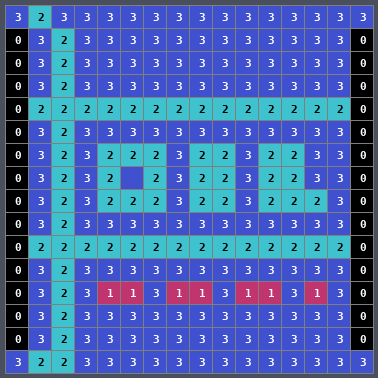
Let’s remove the indexes.
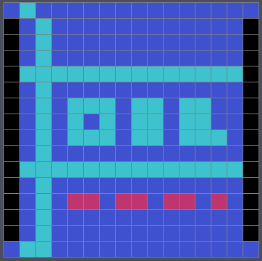
Looks great. But how did we know that the oil drum was using Palette 0? By using the Attribute Table.
Attribute Table
The tiles on screen are further subdivided into blocks, each of which is 4x4 tiles.
The oil drum we’re looking at is in block (1,6). Here the thick lines indicate block boundaries.
A block is subdivided into four regions of 2x2 tiles.
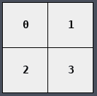
In the attribute table, each block is represented by a single byte. The byte is made of four 2-bit values, one for each 2x2 quadrant of the block. Each value indicates the palette of each quadrant, so a block can have colors from four different palettes
Quad 0 is controlled by Bits 0,1, Quad 1 is controlled by Bits 2,3, Quad 2 is controlled by Bits 4,5, and Quad 3 is controlled by Bits 6,7.
The value in the attribute table at the location for the oil drum is simply 0, so all of the tiles in that block use Palette 0.

That’s pretty boring, so let’s do an example with multiple palettes in different blocks.
Donkey Kong is at the top of the screen. Part of him is in Block (1,1) and part of him is in Block (2,1). He shares a block with a steel girder and a ladder.
With the same procedure as before, we’ll look up each tile in the pattern table, lay them out, combine them, and get a value for each pixel between 0 and 3.
The yellow lines are block boundaries, the white lines are quadrant boundaries, and the gray lines are tile boundaries.
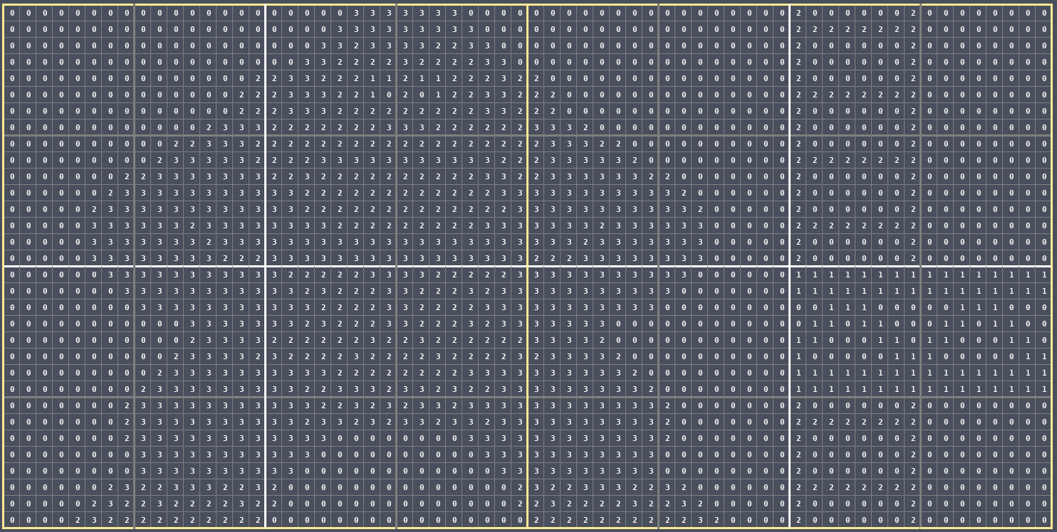
On the left we have Block (1,1) and on the right we have Block (2,1).
The byte in the attribute table for Block (1,1) is AA.

So that means each quadrant in the left block is using Palette 2: black, white, peach, and brown.

We can color in the left block with that palette.
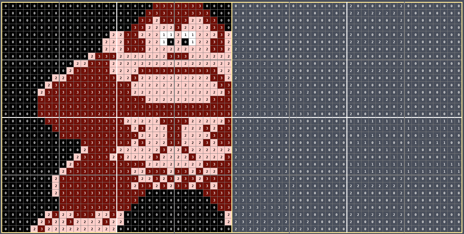
The byte in the attribute table for Block (2,1) is 22:

So that means the upper left quadrant and the bottom left quadrant will use Palette 2 while the upper right quadrant and the bottom right quadrant will use Palette 0 (refer to the diagram above that shows the quadrant order).
We can color in the right block with those two palettes.
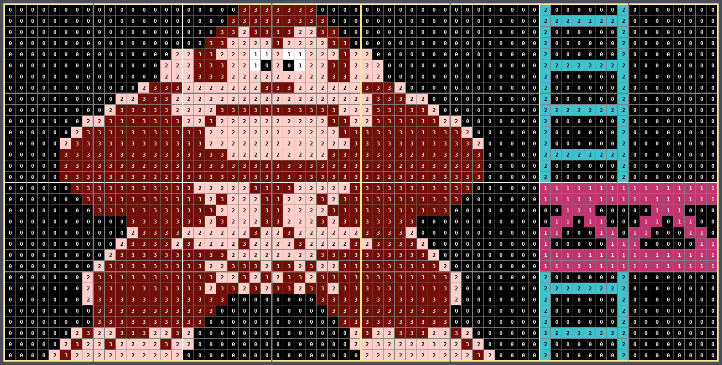
And then without the numbers.
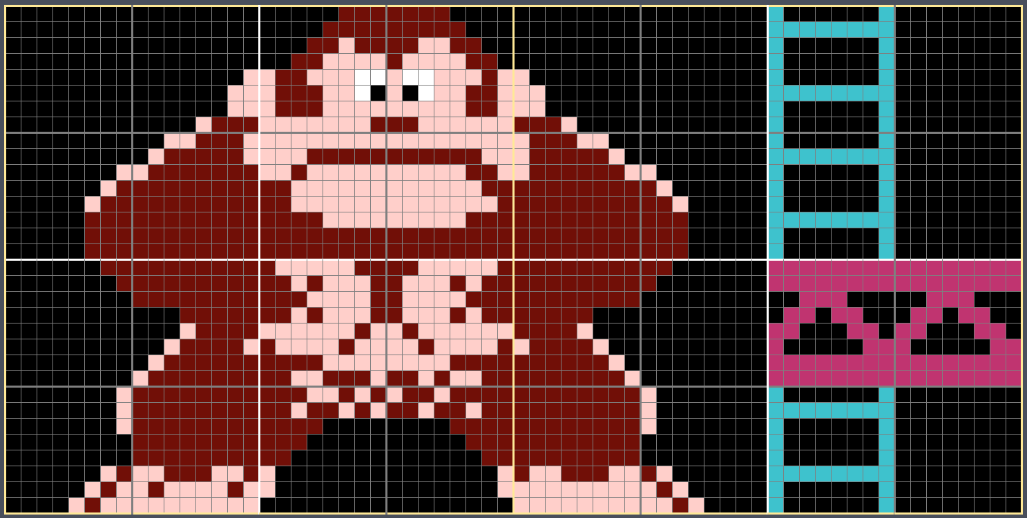
The rendering is now complete. The block on the right has colors from two different palettes while the block on the left does not.
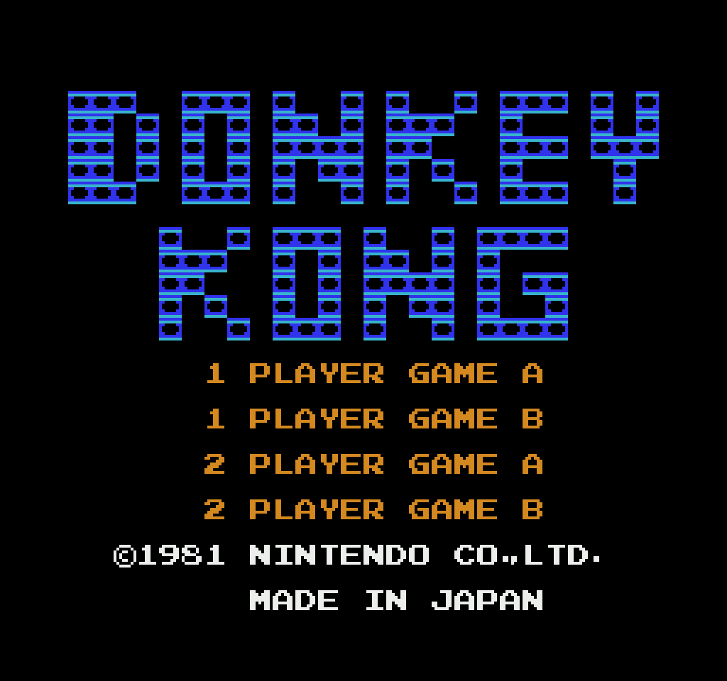
Here is the title screen with the background rendered.
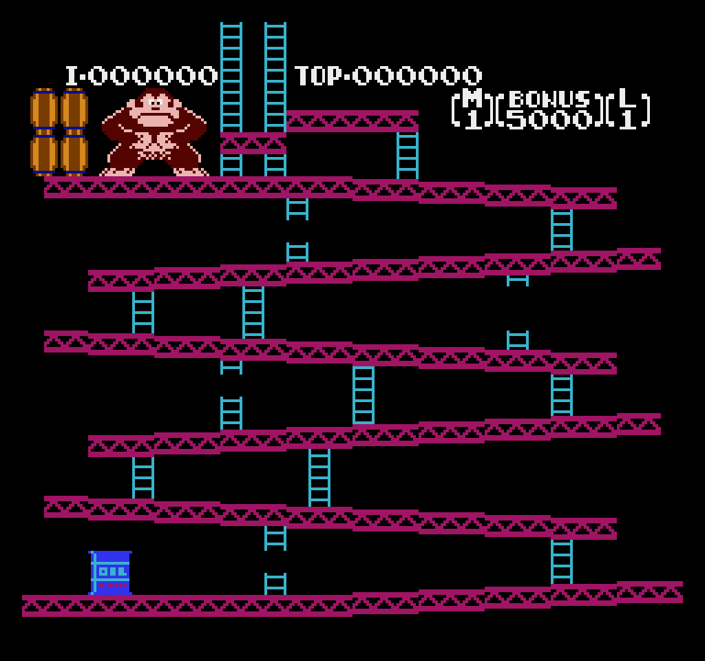
And the game screen with the background rendered.
Sprites
Sprites are rendered differently than the background. Sprites are dynamic: the CPU sends them to the PPU and the PPU puts them into its memory. A single sprite is represented as four bytes: Y-Position, Tile Index, Attributes, and X-Position.
The positions dictate where on screen the sprite is rendered, the tile index is an index into the sprite section of the pattern table, and the attributes dictate the sprite’s appearance.
Let’s look at Mario. He’s composed of four sprites.
We’ll ignore the positions and focus on the Tile ID and the Attributes. We’ll look up the tiles the same way we did for the background and combine the two bytes together to get numbers from 0 to 3.
We now have palette indexes but we don’t know which palette to use. That’s what the attribute byte is for. Bit 1 and Bit 0 are the index into the sprite section of the frame palette (Palette 4 through Palette 7). For Mario, the attributes byte is 00, so Bit 1 and Bit 0 are 0. That means the palette is Palette 0 of the sprite palettes, or Palette 4 of the entire frame palette.

The colors are black, blue, peach, and red. We can color the pixels now.
And without the numbers.
Conclusion
That was a high-level overview of how all of the rendering bits fit together, which is great for creating a mental model of the behavior, but it isn’t enough to do cycle-accurate PPU emulation. For that you need to understand PPU operation at a scanline and cycle level, which will be a task for another day.
Last Edited: Mar 07, 2023
