Programming the ODROID-GO: Input (Part 2)
We need to be able to get player input from the buttons and D-pad on the ODROID-GO.
The Buttons

GPIO
The ODROID-GO has six buttons: A, B, Select, Start, Menu, and Volume.
The buttons are each connected to an individual General Purpose IO (GPIO) pin. GPIO pins can act as inputs (we read from them) or as outputs (we write to them). In the case of buttons, we want to read them.
We need to configure the pins as inputs first and then we can read their state whenever we want. Internally the pins are one of two voltages (3.3V or 0V), but they are translated to integers for us when we read them with the IDF function.
Initialization
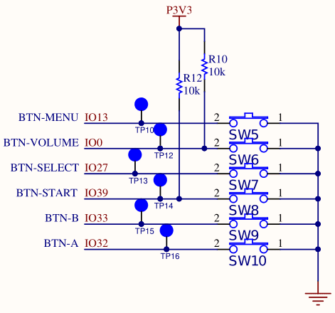
The SW elements in the schematic are the actual physical buttons. When not pressed, the ESP32 pins (IO13, IO0, etc) are tied to 3.3V, meaning that a voltage of 3.3V indicates that the button is not pressed. The logic is the inverse of what you might expect.
IO0 and IO39 have physical resistors on the circuit board that tie the pins high electrically. If the button is not pressed, then the resistor will pull up the pins to a high voltage. When the button is pressed then the current through the pins instead goes to ground, so the pins will read a voltage of 0.
IO13, IO27, IO32, and IO33 do not have resistors because the pins on the ESP32 have internal resistors that we configure to be in pull-up mode.
With that understanding, we can configure the six buttons using the IDF’s GPIO API.
| |
The constants defined at the top each directly correspond to one of the pins in the schematic. We use the gpio_config_t struct to configure each of the six buttons as an input that is pulled up. For IO13, IO27, IO32, and IO33, we must tell the IDF to enable the pull up resistors on those pins. For IO0 and IO39 we don’t actually have to do that since they have physical resistors, but we do so anyway just to keep the configuration neat and tidy.
ESP_ERROR_CHECK is a convenience macro from the IDF that will automatically check the result of any function that returns an esp_err_t value (most of the IDF) and assert if the result is not ESP_OK. It’s good to use for any function where an error is fatal and there’s no point continuing execution. In this case, a game without input isn’t much of a game so an assert is appropriate. We’ll be using that macro a lot.
Reading the Buttons
Now that we’ve configured each of the pins, we can actually read the values.
We read the digital buttons with the function gpio_get_level, but we need to negate the value we receive because the pins are pulled high, so a high signal actually means not pressed and a low signal means pressed. Negating keeps the logic consistent with what a human being expects: 1 means pressed, 0 means not pressed.
| |
D-pad

ADC
The D-pad is connected differently from the buttons. The up and down directions are connected to a single Analog-to-Digital Converter (ADC) pin and the left and right directions are connected to another ADC pin.
Unlike the digital GPIO pins where we could read one of two states (high or low), an ADC converts a continuous analog voltage (e.g., 0V to 3.3V) to a discrete digital value (e.g., 0 to 4095).
I assume the designers of the ODROID-GO set them up this way to save on GPIO pins (only need two analog pins versus four digital). Regardless, it means that our configuration and reading of the pins is a bit more complicated.
Configuration
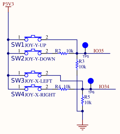
IO35 is the pin connected to the Y-axis of the D-pad and IO34 is the pin connected to the X-axis of the D-pad. We can see that the D-pad connections are a bit more complicated than the digital buttons. There are two switches per axis (SW1 and SW2 for the Y-axis, SW3 and SW4 for the X-axis), each connected to a series of resistors (R2, R3, R4, R5).
For IO35, if neither up or down is pressed, the pin is pulled down to ground through R3, and we will read a value of 0V.
For IO34, if neither left or right is pressed, the pin is pulled down to the ground through R5, and we will read a value of 0V.
If SW1 (up) is pressed, IO35 will read 3.3V. If SW2 (down) is pressed, IO35 will read approximately 1.65V because half of the voltage will be dropped across resistor R2.
If SW3 (left) is pressed, IO34 will read 3.3V. If SW4 (right) is pressed, IO34 will also read approximately 1.65V because half of the voltage is dropped across resistor R4.
Both of these are examples of voltage dividers. When the two resistors in a voltage divider are of identical resistance (100K in this case), the voltage drop is half the input voltage.
With that understanding, we can configure the D-pad:
| |
We set the ADC width to 12 bits so 0V will read as 0 and 3.3V will read as 4095 (2^12). The attenuation says to not attenuate the signal so that we get the full voltage range from 0V to 3.3V.
With 12 bits we can expect to read 0 for nothing pressed, 4096 for up and left, and approximately 2048 for down and right (because the resistors drop half the voltage).
Reading the D-pad
Reading the d-pad is more complicated than the buttons because we need to read the raw value (between 0 and 4095) and interpret it.
| |
ADC_POSITIVE_LEVEL and ADC_NEGATIVE_LEVEL are sane values with some wriggle room to ensure that we always read the correct value.
Polling
We have two options for getting the value of the buttons: polling or interrupts. We could create some input-handling functions and tell the IDF to call those functions whenever the buttons are pressed, or we can just manually poll the state of the buttons whenever we need them.
We’re going to poll. Adding interrupt-driven behavior complicates everything and makes the code flow harder to understand. I’d like to keep everything as simple as possible for as long as possible. We can add interrupts later if we need them.
We’ll create a struct which holds the state of the six buttons and the four D-pad directions. We could create a struct with 10 booleans, or 10 ints, or 10 unsigned ints. However instead we’re going to create a struct using bit fields.
| |
Bitfields are usually avoided in normal desktop programming because they aren’t portable across different machines, but we’re programming for a specific machine so we don’t have to worry about it.
An alternative would be a struct with 10 bools for a total of 10 bytes. Another option is a single uint16_t with bit-shifting and bit-masking macros that can set, clear, and check individual bits. That would work but is not very pretty.
A simple bit field affords us the benefits of both: two bytes of data and named fields.
Demo
We can now poll the state of the inputs inside of our main loop and print the result.
| |
The printf uses \r to overwrite the previous line every time instead of writing out a new one. fflush is required to actually display the line because normally it would flush with the newline character \n.
Source Code
You can find all of the source code here.
Further Reading
Last Edited: Dec 20, 2022