Programming the ODROID-GO: Display (Part 3)
We need to be able to draw pixels onto the LCD screen of the ODROID-GO.
Getting colors onto the screen will be more complicated than reading the state of the input buttons because the LCD actually has brains. The screen is driven by an ILI9341 which is a (very popular) “TFT LCD Single Chip Driver”.
In other words, we communicate with the ILI9341 which then responds to our commands to actually control the pixels on an LCD.
Whenever I say “LCD” or “display” in this post, I actually mean “ILI9341”. When I say “panel” I mean the physical LCD device. We communicate with the ILI9341. It drives the panel.
SPI
The LCD is connected to the ESP32 via SPI (Serial Peripheral Interface).
SPI is a common protocol used to communicate between devices on a circuit board. It uses four signals: MOSI (Master Out Slave In), MISO (Master In Slave Out), SCK (Clock), and CS (Chip Select).
A single master device on the bus coordinates the data transfers by controlling SCK and CS. Multiple devices can be on the same bus with individual CS signals for each. When that device’s CS signal is activated then it is able to send and receive data.
The ESP32 will be the SPI master and the LCD will be a SPI slave. We’ll need to configure the SPI bus with requested settings and then add the LCD to the bus by configuring the proper pins.


The VSPI.XXXX names are just labels for the pins in the schematic, but we can follow the path to the true pin assignments by looking at the LCD and ESP32 sections of the schematic.
- MOSI -> VSPI.MOSI -> IO23
- MISO -> VSPI.MISO -> IO19
- SCK -> VSPI.SCK -> IO18
- CS0 -> VSPI.CS0 -> IO5
There is also IO14 which is a GPIO output that we’ll use to enable the backlight, and IO21 which is connected to the LCD’s DC pin which controls what type of information we’re sending to the display.
We first configure the SPI bus.
| |
We configure the bus with spi_bus_config_t. It requires that we tell it which pins we’re using and the maximum size of a single transfer.
For now we’re going to do one single SPI transfer for an entire framebuffer’s worth of data which is the width of the LCD (in pixels) multipled by the height of the LCD (in pixels) multiplied by the bytes per pixel.
The width is 320, the height is 240, and the depth is 2 bytes (the display expects pixel colors to be 16 bits).
| |
With the bus initialized we need to then add the LCD device to the bus so that we can start communicating with it.
- clock_speed_hz - The LCD specs say that it can understand SPI speeds as high as 40MHz so that’s what we set, but I have successfully communicated with it at 80MHz so we may increase the speed later if we need to.
- spics_io_num - We set the CS pin so that the IDF can toggle the CS signal appropriately when it wants to talk to the display (the SD card interface is also on the SPI bus).
- queue_size - We set this to 1 because we only want a single transaction to be in flight at any time (the entire framebuffer).
- flags - The IDF SPI driver normally inserts dummy bits into the transactions to prevent timing problems when reading from a SPI device, but we’re doing one-way communication (we won’t be reading from the LCD). SPI_DEVICE_NO_DUMMY says that we acknowledge that one-way communication and don’t want the dummy bits inserted.
| |
We also need to set the DC and backlight pins as GPIO outputs. The backlight will be left on permanently while DC will be toggled as needed.
Commands
Communication with the LCD is done in the form of commands. You first send a byte which indicates what command you want to send and then you send the parameters (if there are any). The display knows a byte is a command if the DC pin is driven low. When the DC pin is high then the data it receives is assumed to be the parameters to a previously sent command.
The general flow looks like this:
- Set DC low
- Send a single command byte
- Set DC high
- Send zero or more bytes depending on the requirements of the command
- Repeat 1 through 4
The ILI9341 datasheet is our best friend here. It lists all of the possible commands, their parameters, and how to use them.
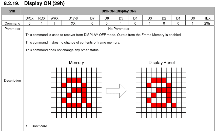
An example of a command with no parameters is Display ON. The command byte is 0x29 but it has no parameters listed.
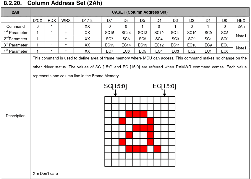
An example of a command with parameters is Column Address Set. The command byte is 0x2A but it lists four required parameters. To use the command you would need to set DC low, send 0x2A, set DC high, and then send the four parameter bytes.
The actual command codes we’ll need are defined in an enum.
| |
We could have instead used a macro (#define SOFTWARE_RESET (0x01u)) but those don’t have symbols in a debugger and they have no scope. We could have used static const integers like we did for the GPIO pins but with an enum we can see at a glance what the data is when it’s passed to a function or a member of a struct: it’s of type CommandCode. Otherwise it would just be a raw uint8_t which doesn’t tell the reader anything at a glance.
Startup
There are a number of commands that must be sent to the display during initialization for it to be able to draw anything.
We’ll define a structure for holding a startup command so that we can define an array of them.
| |
- code is the command code.
- parameters is an array of the command parameters (if any). It’s a static array of size 15 because that’s the most parameters we’ll need. A static array means we don’t have to worry about allocating a dynamic array for each command.
- length is the number of parameters in the parameters array.
With that we can define the list of startup commands.
| |
Commands with no parameters like SOFTWARE_RESET define the parameters initializer list as empty (i.e., all zeroes) and set the length to 0. Commands with parameters fill out the parameters and set the length. It would be nice if we could have the length set automatically for us instead of hardcoding it here (in case we miscount or change the parameters), but I don’t think it’s worth the trouble.
Most of the commands are self-explanatory based on the name, but two of them are not.
MEMORY_ACCESS_CONTROL
- Landscape Mode: The panel’s default orientation is portrait (240x320) but we want to use it in landscape (320x240).
- Top-Left Origin: We set the origin (0,0) to be the top left corner of the display because it makes sense (to me) to write into the framebuffer from top to bottom and left to right.
- BGR Panel: The panel expects pixel colors to be in the form BGR. This became clear when I was setting what I thought were red pixels and they were being displayed as blue.
PIXEL_FORMAT_SET
- 16 bits per pixel: We’re using 16-bit colors.
With the array of startup commands prepared, we can then actually send them to the display.
First we need a function that sends a single command byte to the display. Remember that sending a command differs from sending parameters because we must pull DC low.
| |
The IDF has a spi_transaction_t structure which we fill out when we want to put something onto the SPI bus. We tell it how many bits are in the payload and we provide the payload itself.
We can either provide a pointer to the payload or we can use the struct’s internal tx_data struct which is only four bytes but saves the driver from needing to access external memory. If we use tx_data we must set the SPI_TRANS_USE_TXDATA flag.
Before we actually transmit the transaction we set DC low which indicates to the display that this is a command code.
| |
Sending the parameters is similar to sending the command code except that we use our own buffer this time (data), and we set DC high to indicate to the display that we’re sending parameters. We also don’t set the SPI_TRANS_USE_TXDATA flag because we’re providing our own buffer.
Then we can actually send all of our startup commands.
| |
We iterate through the array of startup commands and send first the command code and the parameters (if there are any).
Drawing a Frame
Once the display is properly initialized we can actually draw to it.
| |
The ILI9341 allows us to only redraw a certain portion of the screen. This may come in handy later if we find our framerate is suffering and we only want to update the parts of the screen that have changed, but for now we’re just going to redraw the entire screen.
Drawing a frame requires that we set up the drawing window by sending COLUMN_ADDRESS_SET with the window width and PAGE_ADDRESS_SET with the window height. Each takes four parameter bytes which describe the window that we’re going to draw into.
UPPER_BYTE_16 and LOWER_BYTE_16 are convenience macros that extract the upper or lower byte of a 16-bit value. The parameters to these commands require that we separate a 16-bit value into two 8-bit values so that’s what we do.
We initiate the draw with MEMORY_WRITE and send all 153,600 bytes of the framebuffer to the display in one go.
There are other ways we could send the framebuffer to the display:
- We could set up another FreeRTOS task that is responsible for coordinating the SPI transactions.
- We could send the frame in a series of transactions instead of a single one.
- We could use a non-blocking send where we initiate the transfer and then continue on doing whatever we were doing.
- We could do some combination of all of them.
We’ll go with the simplest method for now: a single blocking transaction. When we call DrawFrame, a transfer is initiated to the display and our task is put on hold until the transfer completes. If we find later that we can’t achieve a good framerate with this method then we’ll revisit the problem.
RGB565 and Endianness
A normal display (like your monitor) has a bit depth of 24 bits (1.6 million colors): 8 bits of red, 8 bits of green, 8 bits of blue. A pixel is represented in memory as RRRRRRRR|GGGGGGGG|BBBBBBBB.
The LCD on the Odroid instead has a bit depth of 16 bits (65K colors): 5 bits of red, 6 bits of green, and 5 bits of blue. A pixel is presented in memory as RRRRR|GGGGGG|BBBBB. This is called RGB565.
| |
We’ll define a macro that constructs a color in RGB565 form for us. We pass in a red byte, a green byte, and a red byte. It takes the upper five bits of red, the upper six bits of green, and the upper five bits of blue. We take the upper bits because they contain more information than the lower bits.
By shifting to the right first, we get rid of the lower bits that we don’t want. Then we shift left to get the bits we do care about into position. When we OR them all together it constructs the proper 16-bit value.
| |
However, the ESP32 stores data in Little Endian order meaning that the least significant byte is stored in the lowest memory address. For example, the 32-bit value [0xDE 0xAD 0xBE 0xEF] would be stored in memory as [0xEF 0xBE 0xAD 0xDE].
This becomes a problem when sending data to the display because the least-significant byte will be sent first but the LCD expects to receive the most-significant byte first.
| |
We define the macro SWAP_ENDIAN_16 to do a byte swap on a 16-bit value, and we’ll need to use that when constructing a color with the RGB565 macro to get our 16-bit color value in the right order for sending to the display.
Demo
We can set up a simple demo to see the LCD in action. It will clear the framebuffer to black at the beginning of a frame and draw a 50x50 rectangle. We can move the rectangle with the D-pad and change the color with A, B, and Start.
| |
We allocate a framebuffer for the full size of the display: 320 x 240, two bytes per pixel (16-bit color). We allocate it as static so that the buffer will be placed into flash memory. The ODROID-GO has 16MB of flash which is plenty of space for our 150K framebuffer.
We could also allocate the framebuffer in RAM but we would need to ensure that the memory is accessible as Direct Memory Access (DMA) memory for SPI transactions. DMA allows for the SPI peripheral to access the framebuffer without the CPU needing to be involved in the transfer. Without DMA the SPI transactions take much longer to complete.
But if we allocate in RAM we run the risk of not having enough memory, while there is plenty of flash space.
We can see significant tearing. A common way to avoid tearing in a desktop application is to have multiple buffers. Double-buffering, for example, has two: a frontbuffer and a backbuffer. You write to the backbuffer while presenting the frontbuffer. Then you swap them and repeat.
The ESP32 doesn’t have enough DMA-capable RAM to hold two framebuffers (the 4MB of external SPI RAM is unfortunately not DMA-capable) so that option is not available.
The ILI9341 provides a signal (TE) that says when VBLANK is happening so that we could only write to the display when it was not currently drawing. But the Odroid does not have that signal hooked up (or the display module doesn’t) so we can’t access it.
We might be able to come up with a decent solution but we won’t bother for now because our goal at the moment is to just get pixels on the screen.
Source Code
You can find all of the source code here.
Further Reading
Last Edited: Dec 20, 2022