Programming the ODROID-GO: Battery (Part 5)
The ODROID-GO has a lithium-ion battery so we can create a game that can be played on the go. That’s an intriguing concept for someone who grew up playing the original Gameboy.
We thus need a way to be able to query the ODROID-GO’s battery level. The battery is connected to a pin on the ESP32 so we can read the voltage to get a rough estimate of the life remaining.
The Circuit

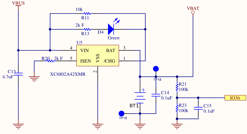
The schematic shows IO36 connected to a voltage VBAT after it’s dropped across a resistor. The two resistors (R21 and R23) create a voltage divider like we saw with the D-pad, and again the resistors are of identical resistance so the voltage drop is half the source voltage.
Due to the voltage divider, IO36 will read a voltage that is half of VBAT. I assume this was done because the ADC pins on the ESP32 would be unable to read a voltage as high as a lithium-ion’s max charge of 4.2V. Whatever the reason, it means we must double the value that we read from the ADC to get the actual voltage.
When we read the value of IO36, we will have a digital value but we will have lost the analog value that it represented. We need a way to interpret the digital value from the ADC as a physical analog voltage.
The IDF allows for ADC calibration which attempts to give you a voltage level based on a reference voltage. This reference voltage (Vref) defaults to 1100mV, but every unit is slightly different due to physical characteristics. The ESP32 in the ODROID-GO has a manually set Vref burned into eFuse which we can use as a more accurate Vref instead.
The procedure will be to configure the ADC calibration initially, and then whenever we want to read the voltage we take a certain number of samples (e.g., 20) to calculate an average reading, then we use the IDF to convert that reading into a voltage. Taking an average helps to eliminate noise and gives a more accurate reading.
Unfortunately there is not a linear relationship between battery voltage and charge. As charge goes down, voltage drops. As charge goes up, voltage rises. But not in any predictable way. All we can say for sure is that if you’re below approximately 3.6V then your battery is getting low, but it is surprisingly difficult to accurately convert a voltage level into a battery percentage.
For our purposes, it doesn’t matter much. We can just do a crude approximation that lets the player know they should charge the device soon, but we won’t agonize over getting it down to the percentage.
Status LED

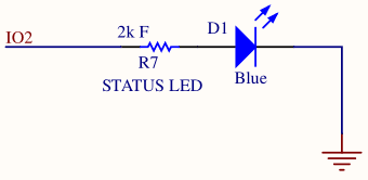
The ODROID-GO has a blue LED on the front below the screen that we can use for whatever purpose we want. We could use it to indicate the device is up and running, but then you’d have a bright blue LED shining into your face when you’re trying to play a game lying in bed at night. So we’ll use it as a way to indicate that the battery is running low (although I’d prefer a red or amber light for that).
To use the LED we need to set IO2 as an output and then set it high or low depending on whether we want the LED to be on or off.
I assume the 2k resistor a current-limiting resistor which ensures we don’t burn out the LED or source too much current from our GPIO pin.
An LED has relatively low resistance, so if you dropped 3.3V across it you would burn out the LED with a surge of current. It’s common for LEDs to have a resistor in series to prevent that.
However, current-limiting resistors for LEDs are normally much smaller than 2k so I’m not sure why R7 is so large.
Initialization
| |
We first set up the LED GPIO as an output so that we can toggle it whenever we want. We then configure the ADC pin like we did for the D-pad, with a bit width of 12 and minimal attentuation.
esp_adc_cal_characterize does some math for us to characterize the ADC in a way that will let us convert a digital reading to a physical voltage later on.
Reading the Battery
| |
We take twenty raw ADC samples from the ADC pin and then divide to get an average reading. As mentioned before, this helps to reduce noise in the readings.
We then use esp_adc_cal_raw_to_voltage to convert the raw value into an actual voltage. We double the returned value because of the voltage divider mentioned earlier: we will be reading a value that is half of the actual battery voltage.
Rather than try to figure out a clever way to scale this voltage to some percentage battery level, we’ll instead just return the plain voltage. It’s then up to the caller to decide what to do with the voltage, whether that means turning it into a percentage or just interpreting it as a high or low value.
The returned value is in millivolts so the caller will need to convert appropriately. This prevents the overhead of a float.
Setting the LED
| |
These two simple functions are all we need to use the LED. We can either turn the light on or turn it off. It’s up to the caller to decide when to do so.
We could have created a task that would monitor the battery voltage periodically and automatically set the light appropriately, but I would rather poll the battery voltage in our main loop and then decide how to set the battery voltage from there.
Demo
| |
We can simply query the battery level in the main loop and, if the voltage is below a threshold, enable the LED to indicate that we should charge the battery. From what I’ve read, 3600mV (3.6V) is a good rule of thumb for a low lithium-ion battery, but batteries are complex.
Source Code
You can find all of the source code here.
Further Reading
Last Edited: Dec 20, 2022