Programming the ODROID-GO: Tile System (Part 8)
As mentioned in Part 7, we’re going to build our backgrounds out of reusable tiles. The dynamic objects in front of the background are sprites, which will be touched on later. Enemies, projectiles, and the player character are examples of sprites.
For the tiles, we’ll fix them to a grid. We’ll use tiles that are 16x16 and our display is 320x240, so that gives us 20x15 tiles to work with. We have the freedom to place 300 tiles on screen at any one time.
The Tile Buffer
We would like to be able to rely on static arrays for storing our tiles rather than use dynamic memory because we don’t want to have to worry about malloc and free and memory leaks and not having enough memory during allocation (this being an embedded system with a limited amount).
If we want to store the tile layout on-screen, and we have 20x15 tiles, then we can think of an array of size 20x15 where each array element is an index into a tile “map”. The tile map contains the actual look of the tile.
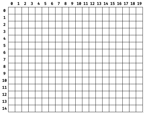
In this diagram, the numbers across the top represent a specific tile’s X coordinate (in tiles) and the numbers on the left represent a specific tile’s Y coordinate (in tiles).
This might be represented in code like:
| |
The problem with this approach is that if we wanted to change what was being displayed on-screen (by changing the contents of a tile), the player would see the tile being swapped.
A solution is to extend the buffer’s area so that we can write to it when it’s off-screen and then it will appear contiguous when displayed.
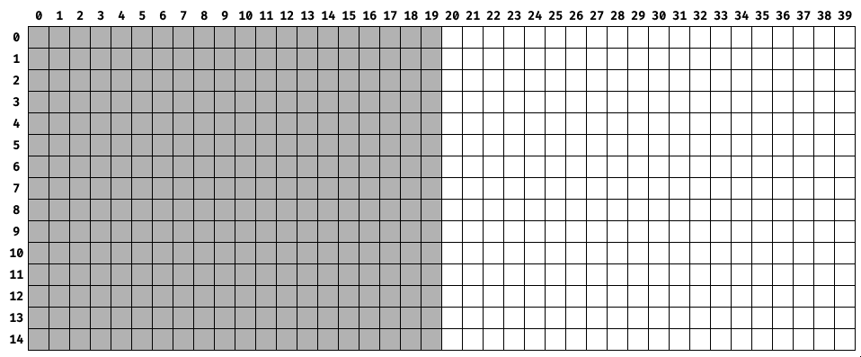
The grey squares indicate the visible “window” into the tile buffer that is what will be rendered to the screen. While the screen is displaying what’s in the grey squares, all of the white squares can have their contents changed without the player being able to see it.
That would be represented in code as an array twice as large in the X-direction.
| |
Choosing a Palette
For now, we’ll use a palette of four greyscale values.
In RGB888, they are:
- 0xFFFFFF (white / 100% value).
- 0xABABAB (light grey / 67% value)
- 0x545454 (dark grey / 33% value)
- 0x000000 (black / 0% value)

We’re avoiding color for now because my art skills are still developing. By using greyscale, I can focus on contrast and form instead of worrying about color theory. Even a limited color palette requires a good artistic eye.
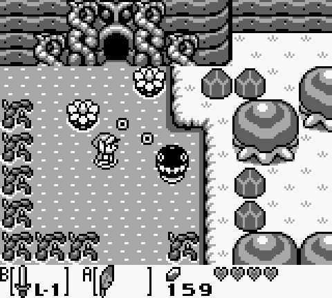
If you doubt the power of 2-bit greyscale, consider the Game Boy which had only four values in its palette. The screen of the original Game Boy had a green tint which which caused the four values to be displayed as shades of green, but the Game Boy Pocket displayed them as true greyscale.
The image below of The Legend of Zelda: Link’s Awakening shows how much can be accomplished even with four values when a talented artist is involved.
For now our tile art will be four squares with a one-pixel gap around the outside and the corners removed. Each will be one of the colors in our palette.
Removing the corners is a minor thing but distinguishes the tiles from each other when viewing them all clustered together which is helpful for grid visualization.

Palette Processing Tool
We’ll keep our palette stored in the JASC Palette file format which is human-readable, easily parsed by a tool, and supported by Aseprite.
Our palette looks like this:
| |
The first two lines are in every PAL file. The third line is the number of entries in the palette. The remaining lines are the palette values as red, green, and blue.
The palette processing tool reads the file, converts each of the colors to RGB565, changes the endianness, and writes the new values out to a header file containing the palette in an array.
The code that does the file-reading and file-writing is similar to the code from Part 7, but the color processing happens here:
| |
The strtok function breaks up a string based on a delimiter. A single space separates the three color values so that’s what we use. Then we create the RGB565 value using bit-shifting and endian-swapping like we did in Part 3.
| |
The output of the tool looks like this:
| |
Tile Processing Tool
We also need a tool that will output a tile’s data in the format the game expects. Each pixel’s value in the BMP file is an index into the palette. We’re going to keep that indirection so that a tile is 16x16 (256) bytes, one byte per pixel. Then at runtime we can look up the tile’s color in the palette.
The tool reads the file, goes through the pixels, and writes their indices to an array in a header.
The file-reading and file-writing code is again similar to the font processing tool, but the relevant array construction happens here:
| |
The index is obtained from the pixel’s location in the BMP file and then written out to the file as an element in a 16x16 array.
| |
The output of the tool when ran on the black tile looks like this:
| |
If you look closely you can see the tile’s shape just by observing the indices. Each 3 means black and each 0 means white.
Frame Window
As an example, we can design a full (and extremely short) “level” which will fill all of the tile buffer. We’ll have four distinct tiles and, to prevent needing to worry about artwork, we’ll use simple artwork where each of the four tiles is a different color of a varying greyscale value.
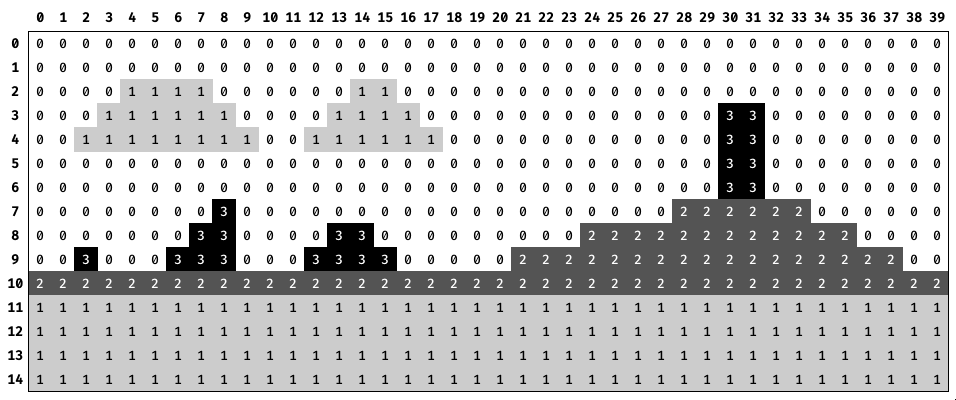
We lay out the four tiles onto the 40x15 level grid to design a simple level layout that will allow us to test our system.
The numbers across the top are the column indices of the entire framebuffer. The numbers across the bottom are the column indices of the frame window. The numbers down the left are the row of both (we have no vertical window movement).
The view from the player’s perspective would look like the animation above. As the window moves to the right, it looks to the player as if the background is moving to the left.
Demo
The number in the upper-left corner is the column number of the left side of the tile buffer window, and the number in the upper-right corner is the column number of the right side of the tile buffer window.
Source Code
You can find all of the source code here.
Last Edited: Dec 20, 2022