Deriving the 3D Rotation Matrix
It took me longer than necessary to understand how a rotation transform matrix rotates a vector through three-dimensional space. Not because it’s a difficult concept but because it is often poorly explained in textbooks. Even the most explanatory book might derive the matrix for a rotation around one axis (e.g., x) but then present the other two matrices without showing their derivation.
I’ll explain my own understanding of their derivation in hopes that it will enlighten others that didn’t catch on right away.
Basis Vectors
Any vector in space, whether 2D or 3D, can be thought of as a combination of other vectors called the basis vectors. The basis vectors are of unit length and lie along the coordinate axes of the space. The one that lies along the x-axis is \(\hat{\mathbf{i}}\). The one that lies along the y-axis is \(\hat{\mathbf{j}}\). And the one that lies along the z-axis is \(\hat{\mathbf{k}}\).
\( \hat{\mathbf{i}} = \begin{bmatrix} 1 \\ 0 \\ 0 \end{bmatrix} \hat{\mathbf{j}} = \begin{bmatrix} 0 \\ 1 \\ 0 \end{bmatrix} \hat{\mathbf{k}} = \begin{bmatrix} 0 \\ 0 \\ 1 \end{bmatrix} \)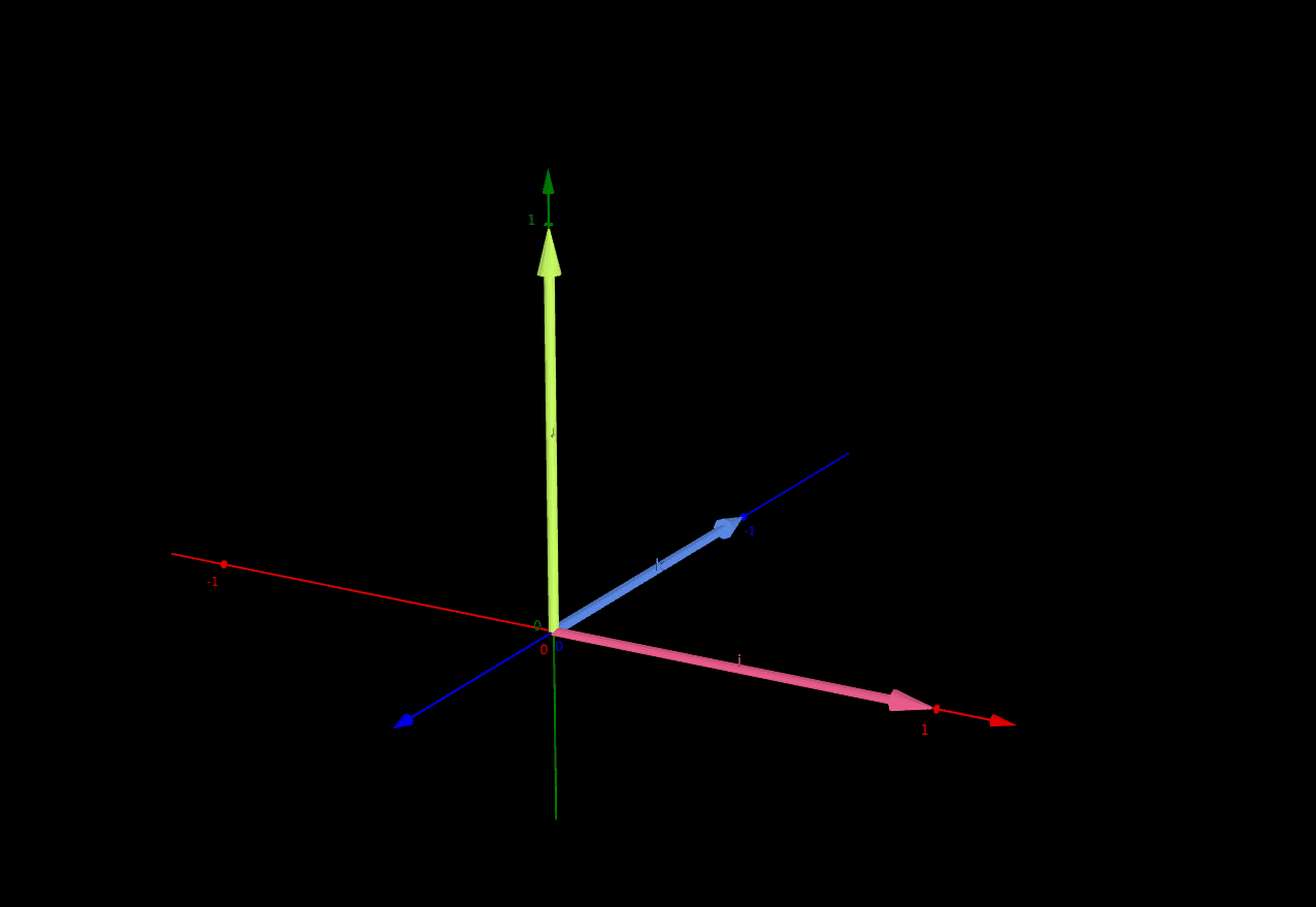
The components of the basis vectors are x, y, and z, corresponding to the x-, y-, and z-axes.
\( \hat{\mathbf{i}} = \begin{bmatrix} i_x \\ i_y \\ i_z \end{bmatrix} \hat{\mathbf{j}} = \begin{bmatrix} j_x \\ j_y \\ j_z \end{bmatrix} \hat{\mathbf{k}} = \begin{bmatrix} k_x \\ k_y \\ k_z \end{bmatrix} \)A combination of these vectors can create any other vector. When you list a vector composed of three numbers, you’re actually listing scalar multiples of the basis vectors.
For example, consider the following vector \(\vec{v}\):
\( \vec{v} = \begin{bmatrix} 2 \\ 3 \\ 4 \end{bmatrix} \)It can be thought of as being composed of a combination of the basis vectors:
\( \vec{v} = 2\hat{\mathbf{i}} + 3\hat{\mathbf{j}} + 4\hat{\mathbf{k}} = 2 \begin{bmatrix} 1 \\ 0 \\ 0 \end{bmatrix} + 3 \begin{bmatrix} 0 \\ 1 \\ 0 \end{bmatrix} + 4 \begin{bmatrix} 0 \\ 0 \\ 1 \end{bmatrix} = \begin{bmatrix} 2 \\ 3 \\ 4 \end{bmatrix} \)A transformation matrix like transforms the basis vectors. The transformation then applies to all vectors that are composed of those basis vectors. Creating a transformation matrix is then as simple as thinking about how to transform the individual basis vectors. This is key to understanding how to construct the rotation matrix.
2D Rotation
We’ll start in 2D first as it’ll make the 3D cases more clear later.
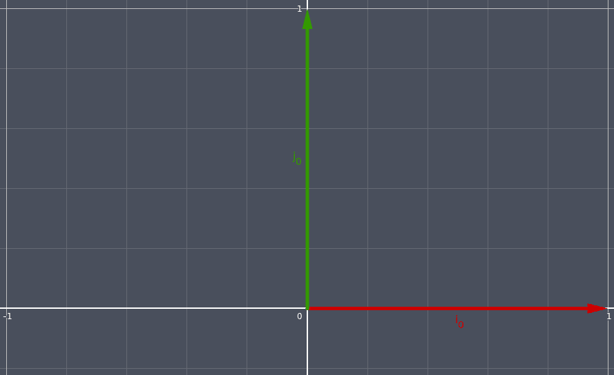
We begin with the basis vectors in their standard form, called \(\hat{\mathbf{i_0}}\)and \(\hat{\mathbf{j_0}}\).
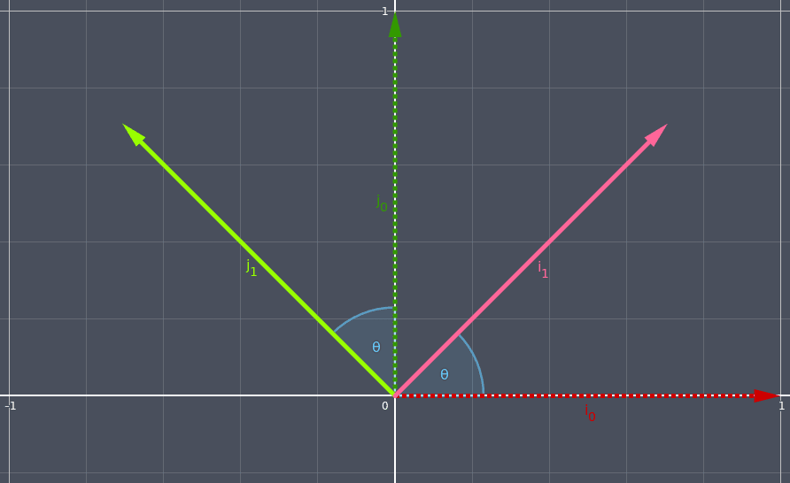
We rotate the basis vectors counter-clockwise (a positive rotation) by some amount θ. We’ll call the new basis vectors \(\hat{\mathbf{i_1}}\)and \(\hat{\mathbf{j_1}}\).
If we draw lines from the tips of the rotated vectors to the x-axis and y-axis, we create two triangles. The sides of the triangles parallel to the x-axis are the x-components of the new rotated vectors, and the sides of the triangles parallel to the y-axis are y-components of the new rotated vectors.
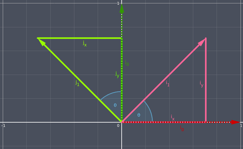
Using trigonometry, we can get the values of the x-components and y-components using sine and cosine.
\( \begin{aligned} cos(\theta) = \frac{adjacent}{hypotenuse} \\ \\ sin(\theta) = \frac{opposite}{hypotenuse} \end{aligned} \)Because the standard basis vectors are of unit length (i.e., 1), and they are the hypotenuses of these two triangles, things can be simplified.
\( \begin{aligned} cos(\theta) = \frac{adjacent}{1} \\ \\ adjacent = cos(\theta) \\ \\ \\ sin(\theta) = \frac{opposite}{1} \\ \\ opposite = sin(\theta) \end{aligned} \)For the red triangle, the side adjacent the angle of rotation is the x-component of \(\hat{\mathbf{i_1}}\)and the side opposite the angle of rotation is the y-component of \(\hat{\mathbf{i_1}}\).
\( \begin{aligned} i_x = cos(\theta) \\ i_y = sin(\theta) \end{aligned} \)For the green triangle, the side adjacent the angle of rotation is the y-component of \(\hat{\mathbf{j_1}}\)and the side opposite the angle of rotation is the x-component of \(\hat{\mathbf{j_1}}\). The x-component is on the left side of the y-axis so it must be negated.
\( \begin{aligned} j_x = -sin(\theta) \\ j_y = cos(\theta) \end{aligned} \)With that information we can build a 2x2 matrix that will calculate the new values of the rotated vectors. The left column of the matrix represents the transformation of the \(\hat{\mathbf{i}}\)basis vector and the right column represents the transformation of the \(\hat{\mathbf{j}}\)basis vector.
\( \begin{bmatrix} cos(\theta) & -sin(\theta) \\ sin(\theta) & cos(\theta) \end{bmatrix} \)We can verify that this does what we want by multiplying the matrix by each of the standard basis vectors to produce the results we derived up above with analyzing the triangles.
For \(\hat{\mathbf{i}}\):
\( \begin{bmatrix} cos(\theta) & -sin(\theta) \\ sin(\theta) & cos(\theta) \end{bmatrix} \begin{bmatrix} 1 \\ 0 \end{bmatrix} = \begin{bmatrix} cos(\theta) \\ sin(\theta) \end{bmatrix} \)For \(\hat{\mathbf{j}}\):
\( \begin{aligned} \begin{bmatrix} cos(\theta) & -sin(\theta) \\ sin(\theta) & cos(\theta) \end{bmatrix} \begin{bmatrix} 0 \\ 1 \end{bmatrix} = \begin{bmatrix} -sin(\theta) \\ cos(\theta) \end{bmatrix} \end{aligned} \)3D Rotation
3D rotation is very similar except that of course we need an extra dimension. But since we’re rotating around a fixed axis, it behaves exactly like the 2D case with one of the dimensions ignored.
Our goal is to construct three 3x3 matrices, one for each rotation about one of the axes.
\( M_{x} = \begin{bmatrix} ? & ? & ? \\ ? & ? & ? \\ ? & ? & ? \end{bmatrix} M_{y} = \begin{bmatrix} ? & ? & ? \\ ? & ? & ? \\ ? & ? & ? \end{bmatrix} M_{z} = \begin{bmatrix} ? & ? & ? \\ ? & ? & ? \\ ? & ? & ? \end{bmatrix} \)Of the 3x3 rotation matrix, the left column is the transformation of \(\hat{\mathbf{i}}\), the middle column is the transformation of \(\hat{\mathbf{j}}\), and the right column is the transformation of \(\hat{\mathbf{k}}\).
3D Rotation Around the Z-Axis
We’ll start with rotation around the z-axis because it’s going to look very familiar.
If we think of z as pointing into the screen, and we look at the vectors straight on, then we see a familiar scenario.

\(\hat{\mathbf{k}}\)is pointing into the screen so we can’t see it, but we have our familiar \(\hat{\mathbf{i}}\)pointing to the right and \(\hat{\mathbf{j}}\)pointing up.
If we rotate counter-clockwise by an angle, then we are again presented with the triangles from earlier.

We know that when rotating about the z-axis we don’t want to affect \(\hat{\mathbf{k}}\), so we put the basis vector unchanged in its column.
\( M_{z} = \begin{bmatrix} ? & ? & 0 \\ ? & ? & 0 \\ ? & ? & 1 \end{bmatrix} \)We also know that when rotating about the z-axis we don’t want to affect the z-components of the other basis vectors, so we put 0s in the z-components of them.
\( M_{z} = \begin{bmatrix} ? & ? & 0 \\ ? & ? & 0 \\ 0 & 0 & 1 \end{bmatrix} \)We determined earlier (in the 2D rotation section) the components of \(\hat{\mathbf{i}}\).
\( \begin{aligned} i_x = cos(\theta) \\ i_y = sin(\theta) \end{aligned} \)We also determined earlier the components of \(\hat{\mathbf{j}}\).
\( \begin{aligned} j_x = -sin(\theta) \\ j_y = cos(\theta) \end{aligned} \)We’re interested in the x- and y-components of \(\hat{\mathbf{i}}\)and \(\hat{\mathbf{j}}\)because we’re rotating around the z-axis so we want the z-components to remain fixed. So we can take the exact same 2x2 matrix that we calculated earlier and put that into the empty spots in \(M_{z}\).
\( M_{z} = \begin{bmatrix} i_x & j_x & 0 \\ i_y & j_y & 0 \\ 0 & 0 & 1 \end{bmatrix} \)We can then fill in the values by looking at the triangle diagram.
\( m_{z} = \begin{bmatrix} cos(\theta) & -sin(\theta) & 0 \\ sin(\theta) & cos(\theta) & 0 \\ 0 & 0 & 1 \end{bmatrix} \)3D Rotation Around the X-Axis
If we do the same with the x-axis that we did with the z-axis, we get a very similar diagram with two triangles as would be expected. The difference, however, is that now we’re dealing with y-components and z-components. The x-components of the basis vectors are fixed in place because we’re rotating around the x-axis.
In the diagram below, the y-axis is pointing to the right, the z-axis up, and the x-axis into the screen (remember: left-handed).
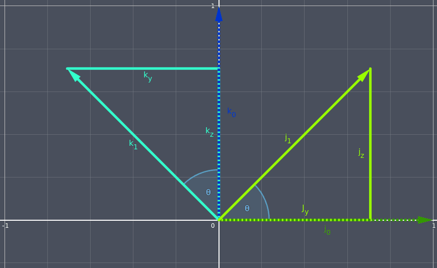
For the green triangle, the side adjacent the angle of rotation is the y-component of \(\hat{\mathbf{j_1}}\)(because it’s parallel to the y-axis) and the side opposite the angle of rotation is the z-component of \(\hat{\mathbf{j_1}}\)(because it’s parallel to the z-axis).
\( \begin{aligned} j_y = cos(\theta) \\ j_z = sin(\theta) \end{aligned} \)For the teal triangle, the side adjacent the angle of rotation is the z-component of \(\hat{\mathbf{k_1}}\)and the side opposite the angle of rotation is the y-component of \(\hat{\mathbf{k_1}}\). The y-component is on the left side of the z-axis so it must be negated.
\( \begin{aligned} k_y = -sin(\theta) \\ k_z = cos(\theta) \end{aligned} \)We again use the same sine and cosine operations but now their result is applied to the y- and z-components instead of x- and y-components.
We know that when rotating about the x-axis we don’t want to affect \(\hat{\mathbf{i}}\), so we put the basis vector unchanged in its column.
\( M_{x} = \begin{bmatrix} 1 & ? & ? \\ 0 & ? & ? \\ 0 & ? & ? \end{bmatrix} \)We also know that when rotating about the x-axis we don’t want to affect the x-components of the other basis vectors, so we put 0s in the x-components of them.
\( M_{x} = \begin{bmatrix} 1 & 0 & 0 \\ 0 & ? & ? \\ 0 & ? & ? \end{bmatrix} \)The middle column of the matrix represents \(\hat{\mathbf{j}}\)and so we will fill its y- and z-components.
The right column of the matrix represents \(\hat{\mathbf{k}}\)and so we will fill its y- and z-components.
\( M_{x} = \begin{bmatrix} 1 & 0 & 0 \\ 0 & j_y & k_y \\ 0 & j_z & k_z \end{bmatrix} \)We can then fill in the values by looking at the triangle diagram.
\( M_{x} = \begin{bmatrix} 1 & 0 & 0 \\ 0 & cos(\theta) & -sin(\theta) \\ 0 & sin(\theta) & cos(\theta) \end{bmatrix} \)3D Rotation Around the Y-Axis
Lastly we can do the same again with the y-axis and again we have two triangles. This time we’re dealing with x- and z-components because the y-axis is locked.
In the diagram below, the z-axis is pointing to the right, the x-axis up, and the y-axis into the screen.
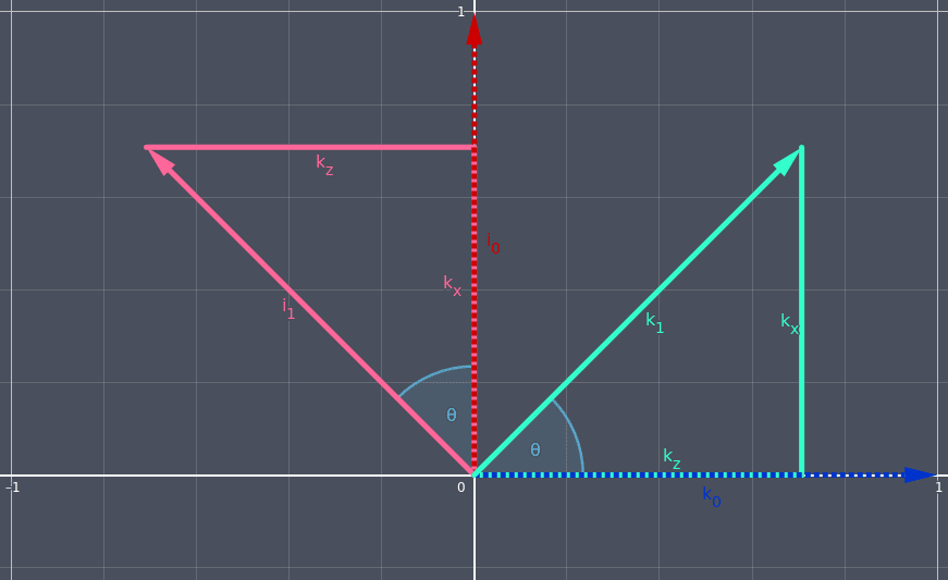
For the teal triangle, the side adjacent the angle of rotation is the z-component of \(\hat{\mathbf{k_1}}\)and the side opposite the angle of rotation is the x-component of \(\hat{\mathbf{k_1}}\).
\( \begin{aligned} k_x = sin(\theta) \\ k_z = cos(\theta) \end{aligned} \)For the red triangle, the side adjacent the angle of rotation is the x-component of \(\hat{\mathbf{i_1}}\)and the side opposite the angle of rotation is the z-component of \(\hat{\mathbf{k_1}}\). The z-component is on the left side of the x-axis so it must be negated.
\( \begin{aligned} i_x = cos(\theta) \\ i_z = -sin(\theta) \end{aligned} \)We know that when rotating about the y-axis we don’t want to affect \(\hat{\mathbf{j}}\), so we put the basis vector unchanged in its column.
\( M_{y} = \begin{bmatrix} ? & 0 & ? \\ ? & 1 & ? \\ ? & 0 & ? \end{bmatrix} \)We also know that when rotating about the y-axis we don’t want to affect the y-components of the other basis vectors, so we put 0s in the y-components of them.
\( M_{y} = \begin{bmatrix} ? & 0 & ? \\ 0 & 1 & 0 \\ ? & 0 & ? \end{bmatrix} \)The left column of the matrix represents \(\hat{\mathbf{i}}\)and so we will fill its x- and z-components.
The right column of the matrix represents \(\hat{\mathbf{k}}\)and so we will fill its x- and z-components.
\( M_{y} = \begin{bmatrix} i_x & 0 & k_x \\ 0 & 1 & 0 \\ i_z & 0 & k_z \end{bmatrix} \)We can then fill in the values by looking at the triangle diagram.
\( M_{y} = \begin{bmatrix} cos(\theta) & 0 & sin(\theta) \\ 0 & 1 & 0 \\ -sin(\theta) & 0 & cos(\theta) \end{bmatrix} \)Summary
The key things to remember are that each column of the matrix transforms the basis vectors, and that the derivations can be done by drawing triangles and doing simple trigonometry. If you forget the matrices (which you will) and are unable to look them up for some reason (like a job interview), you now have the intuition to derive them yourself.
Rotation around the x-axis:
\( M_{x} = \begin{bmatrix} 1 & 0 & 0 \\ 0 & cos(\theta) & -sin(\theta) \\ 0 & sin(\theta) & cos(\theta) \end{bmatrix} \)Rotation around the y-axis:
\( M_{y} = \begin{bmatrix} cos(\theta) & 0 & sin(\theta) \\ 0 & 1 & 0 \\ -sin(\theta) & 0 & cos(\theta) \end{bmatrix} \)Rotation around the z-axis:
\( M_{z} = \begin{bmatrix} cos(\theta) & -sin(\theta) & 0 \\ sin(\theta) & cos(\theta) & 0 \\ 0 & 0 & 1 \end{bmatrix} \)Last Edited: Dec 20, 2022